Getting started
This short introduction will guide you through the first steps of using Plaquette.
Step 1: Install Plaquette
If you do not have Arduino installed on your machine you need to download and install the Arduino IDE for your platform.
Once Arduino is installed, please install Plaquette as an Arduino library following these instructions.
Step 2: Your first Plaquette program
We will begin by creating a simple program that will make the built-in LED on your microcontroller blink.
Create a new sketch
Create a new empty sketch by selecting File > New.
Note
New Arduino sketches are initialized with some “slug” starting code. Make sure to erase the content of the sketch before beginning. You can use Edit > Select All and then click Del or Backspace.
Include library
Include the Plaquette library by typing:
#include <Plaquette.h>
Create an output unit
Now, we will create a new unit that will allow us to control the built-in LED:
DigitalOut myLed(13);
In this statement, DigitalOut is the type of unit that we are
creating (there are other types of units, which we will describe later).
DigitalOut is a type of software unit that can represent one of the many
hardware pins for digital output on the Arduino board. One way to think about
this is that the DigitalOut is a “virtual” version of the Arduino pin.
These can be set to one of two states: on or off.
The word myLed is a name for the object we are creating.
Finally, 13 is an argument that specifies the hardware pin that the object
myLed corresponds to on the board. In English, the statement would thus read
as: “Create a unit of type DigitalOut named myLed on pin 13.”
Tip
Most Arduino boards have a pin connected to an on-board LED in series with a resistor and on
most boards, this LED is connected to digital pin 13. The constant LED_BUILTIN is
the number of the pin to which the on-board LED is connected.
Create an input unit
We will now create another unit which will generate a signal switching regularly
from on to off. This signal will be sent to the LED to change its state, thus making
it blink. To do so, we will use the Wave unit type to generate a square
wave oscillating between on and off
at a regular period of 2 seconds:
Wave myWave(2.0);
Note
The argument here is used not to specify a pin number (as for the DigitalOut
unit) but rather to define the period of oscillation. Each object type provides a unique set
of argument combinations and definitions specific to their usage..
Create the step() function
Now that you have your input and your output units, you need to tell Plaquette how they interact. For this, we will create a function. A function is a self-contained block of code that defines a series of operation.
The function we will create is called step(): it is called repetitively and indefinitely
by Plaquette during the course of the program (like the
loop()
function in Arduino).
Our step() function will simply send the signal generated by the myWave input unit
to the myLed output unit. We will do this by using Plaquette’s special >> operator:
void step() {
  myWave >> myLed;
}
In plain English, the statement myWave >> myLed reads as: “Take the
value generated by myWave and put it in myLed.”
Note
It is beyond the scope of this introduction to explain the keyword void. If you
are curious, however, you can read the Arduino documentation.
Upload sketch
Upload your sketch to the Arduino board. You should see the LED on the board blinking once every two seconds at a regular pace.
Et voilà!
Full code
#include <Plaquette.h>

DigitalOut myLed(13);

Wave myWave(2.0);

void step() {
  myWave >> myLed;
}
Step 3 : Experiment!
So far so good. Let’s see if we can push this a bit further.
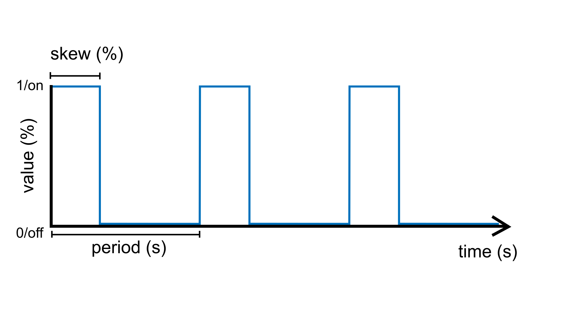
The Wave unit type accepts two arguments that allow you to create a wide range of rhythmic patterns:
Wave myWave(period, skew);
period(which we have already used) can be any positive number representing the period of oscillation (in seconds)skew(optional) can be any number between 0.0 (0%) and 1.0 (100%), and represents the proportion of the period during which the signal is on. Default value: 0.5 (50%).
Note
We call this step the construction or instantiation of the object myWave.
Adjust the period
Try changing the first argument (period) in the square oscillator unit to change
the period of oscillation.
Wave myWave(1.0);for a period of one secondWave myWave(2.5);for a period of 2.5 secondsWave myWave(10.0);for a period of 10 secondsWave myWave(0.5);for a period of half a second (500 milliseconds)
Important
Don’t forget to re-upload the sketch after each change.
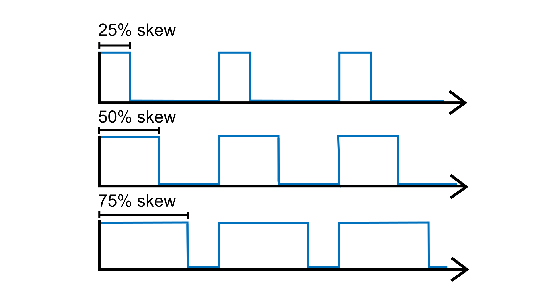
Skew that wave!
Now try adding a second argument (skew) to control the oscillator’s
skew. For a fixed period, try changing
the duty cycle to different percentages between 0.0 and 1.0.
Wave myWave(2.0, 0.5);for a skew of 50% (default)Wave myWave(2.0, 0.25);for a skew of 25%Wave myWave(2.0, 0.75);for a skew of 75%Wave myWave(2.0, 0.9);for a skew of 90%
Understanding parameters
In Plaquette, a parameter is a property of a unit that you can read and modify while your program is running. Parameters give you dynamic control over your units, allowing you to change their behavior in real-time.
The Wave unit has several parameters:
period: the duration of one complete cycle (in seconds)skew: the proportion of the cycle during which the signal is on (0.0 to 1.0)frequency: the number of cycles per second (in Hz)bpm: the number of cycles per minute (beats-per-minute)jitter: adds randomness to the timing (0.0 to 1.0)phaseShift: the phase offset as a propoption of period (0.0 to 1.0)phase: the oscillation phase as a propoption of period (0.0 to 1.0)
You may have noticed that when we created our wave, we were able to set some of these parameters (period and skew) directly using the constructor arguments:
Wave myWave(2.0);        // sets the period parameter to 2 seconds
Wave myWave(2.0, 0.25);  // sets period to 2 seconds and skew to 25%
But what about the other parameters like frequency or bpm? Let’s first see how
we can initialize those at startup using the . (dot) operator.
Initialize parameters in the begin() function
The begin() function is automatically called only once at the beginning of the
sketch (just like the setup()
function in Arduino). It is a good place to initialize parameters that cannot be set
through constructor arguments.
For example, to set our wave’s frequency instead of its period:
void begin() {
  myWave.frequency(10); // 10 Hz = 10 times per second
}
Or, if you prefer to set the frequency in beats-per-minute (BPM):
myWave.bpm(120); // 120 cycles per minute
Note
Setting the frequency will override the period (and vice versa), since period is simply the inverse of frequency.
Change parameters of a unit during runtime
What if we wanted to change the parameters of the oscillator during runtime rather than
just at the beginning? The Wave unit type allows real-time modification of its parameters
by calling one of its functions using the . (dot) operator.
For example, to change the frequency while the program is running, we would simply need
call frequency(value) function inside the step() function rather than the begin()
function:
void step() {
  myWave.frequency(newFrequency); // change the frequency
  myWave >> myLed;
}
Of course, to accomplish our goal, we need a way to change the value newFrequency
during runtime. We can accomplish this in many different ways, but let’s try something
simple: we will use another wave to modulate our wave’s frequency.
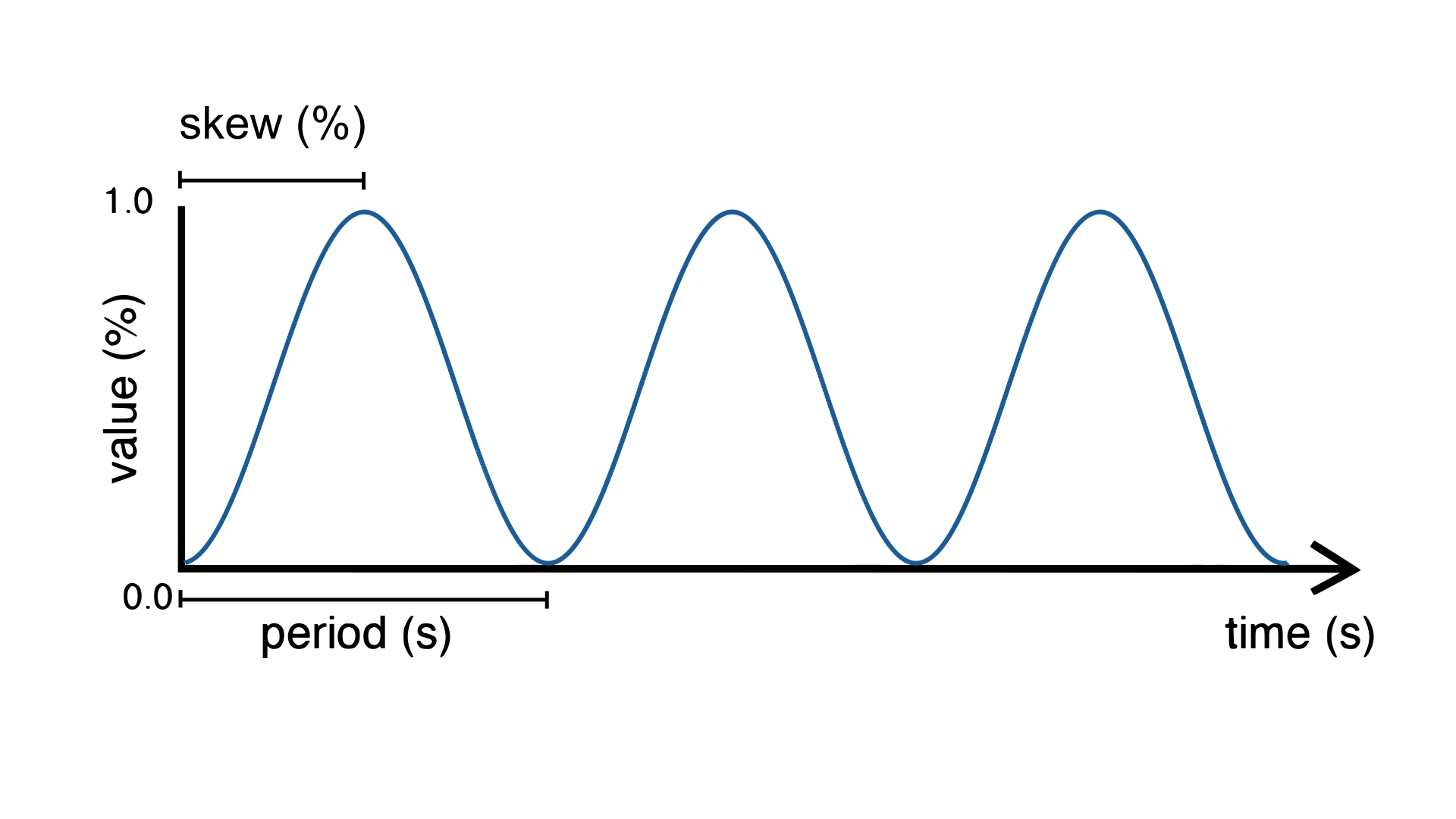
For this, we will be using another type of wave called a sine wave and will use its
outputs to change the period of myWave.
Wave myModulator(SINE, 20.0);
This wave will oscillate smoothly from 0 to 1 every 20 seconds.
void step() {
  myWave.frequency(myModulator); // change the frequency of myWave using myModulator
  myWave >> myLed;
}
Upload the sketch and you should see the LED blinking as before, with the difference that the blinking speed will now change from blinking very fast (in fact, infinitely fast, with a period of zero seconds!) to very slow (period of 20 seconds).
You can take advantage of the >> operator to change a unit’s parameter with a more
expressive syntax:
myModulator >> myWave.Frequency(); // equivalent to: myWave.frequency(myModulator);
Important
Notice the use of the capitalized first letter in the above call: myWave.Frequency().
This tells Plaquette that we are flowing a value to a parameter slot rather than directly
reading or setting a parameter.
In Plaquette, most functions are written in lowercase (such as frequency()) and are used
to read or set a value directly. Functions starting with a capital letter (such as
Frequency()) instead provide a connection point for that parameter, making it possible
to connect it seamlessly using the >> operator, without confusing parameter slots with
normal function calls.
Upload the sketch and you should see the LED blinking as before, with the difference that the blinking speed will now change from blinking very slowly (in fact, infinitely slowly, with a frequency of zero-times-per-seconds!) to one time per second.
Tip
You can try modulating other parameters of the wave instead of its frequency:
myModulator >> myWave.Skew();
myModulator >> myWave.Period();
This table summarizes the different ways one can access and modify a unit’s parameters:
Name |
Format |
Preferred use |
Example use |
|---|---|---|---|
Read parameter |
|
Read the current value of a parameter (monitoring, logic, debugging). |
|
Set parameter |
|
Initialize or directly update a parameter from a value or expression. |
|
Parameter flow |
|
Continuously control a parameter (modulation, mapping). |
|
Caution
You cannot use the >> operator with any objects or functions: only Plaquette
units and parameters are supported. Not all functions provided by a unit are parameters.
Read the unit’s documentation for more details.
Tip
If you want to visualize the values of both waves on your computer, you can print them
on the serial port. For this you need to create a Plotter. You can do so by adding
the following line at the top of your sketch:
Plotter plotter(115200);
The Plotter unit type accepts an argument to define baud rate, or the speed of message
transmission. In this guide we use 115200, which is a standard speed for serial communication.
Then, add the following code to your step() function to send the values to the plotter:
myWave >> plotter;
myModulator >> plotter;
Finally, launch the Arduino Serial Plotter by selecting Tools > Serial Plotter. Make sure to select the same baud rate (115200). You should see a live visualization of the two waves.
Use a button
Now let’s try to do some very simple interactivity by using a simple switch or button. For this we will be using the internal pull-up resistor available on Arduino boards for a very simple circuit. One leg of the button should be connected to ground (GND) while the other should be connected to digital pin 2.
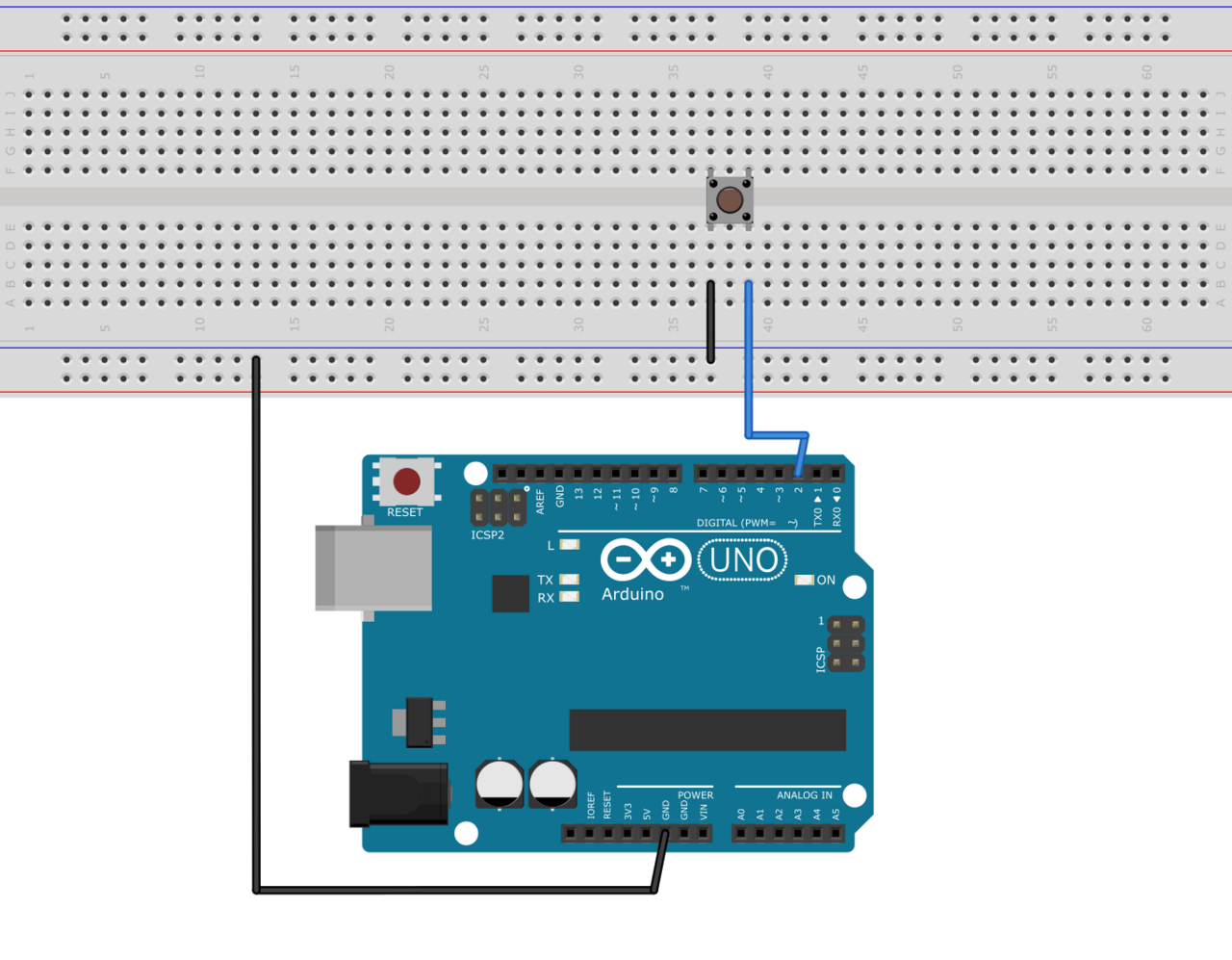
Tip
If you do not have a button or switch, you can just use two electric wires: one connected to ground (GND) and the other one to digital pin 2. When you want to press the button, simply touch the wires together to close the circuit.
Declare the button unit with the other units at the top of your sketch:
DigitalIn myButton(2, INTERNAL_PULLUP);
You will notice that the type of this unit (DigitalIn) resembles that of our LED-controlling
unit (DigitalOut). This is because both units have something in common: they have only two states:
either on or off, high or low, true or false, one or zero, hence the adjective Digital. However,
while the LED is considered an output or actuator (Out) our button is rather an input or sensor
(In).
Note
If you are curious, you might also want to know that there is an AnalogIn and an AnalogOut types which support sensors and actuators that work with continuous values between 0 and 1 (0% to 100%).
Now, let’s use this button as a way to control whether the LED blinks or not. For this, we will need to use the value of the button as part of a condition for an if…else statement.
if (myButton)
  myWave >> myLed;
else
  0 >> myLed;
Full code
#include <Plaquette.h>

DigitalOut myLed(13);

Wave myWave(2.0);

Wave myModulator(SINE, 20.0);

DigitalIn myButton(2, INTERNAL_PULLUP);

void step() {
  myModulator >> myWave.Period();

  if (myButton)
    myWave >> myLed;
  else
    0 >> myLed;
}
Learning More
Built-in Examples
You will find more examples here or directly from the Arduino software in File > Examples > Plaquette including:
Using analog inputs such as a photocells or potentiometers
Using analog outputs
Serial input and output
Using wave generators
Time management
Ramps
Basic filtering (smoothing, re-scaling)
Peak detection
Event-driven programming
Controlling servomotors
The Plaquette Reference
The online reference can be accessed here or directly from the sidebar of the Plaquette website. It provides detailed technical documentation for every available unit and function in Plaquette. This reference serves as a go-to resource for understanding the specifics of each component, including their parameters, methods, and behavior.
Here are the key sections of the reference:
Base Units: Introduces foundational units like DigitalIn, DigitalOut, AnalogIn, and AnalogOut. These are the building blocks for interfacing with hardware pins.
Generators: Covers the signal generators Wave and Ramp. These are used to create various types of regular signals.
Timing: Focuses on units related to time management such as Metronome for periodic events and Alarm for duration-based functionality.
Filters: Discusses tools for smoothing, scaling, or normalizing signals, as well as detecting peaks.
Communication: Presents units used for monitoring and plotting data, allowing information to flow between embedded device and computer.
Functions: Explains helper functions for tasks like value mapping, signal transformations, and conversions.
Structure: Describes core structural functions and operators.
Extra: Contains miscellaneous units and features.
What’s Next?
With the basics covered, you are now ready to dive deeper into Plaquette’s capabilities. Explore the rest of the guide to learn about specific features and advanced techniques:
Inputs and Outputs: Learn how to use Plaquette to handle a variety of inputs and outputs, including analog, digital, and specialized sensors or actuators.
Generating Waveforms: Understand the different types of wave generators available and how they can be used for oscillatory or periodic behavior.
Working with Time: Delve into Plaquette’s timing management units to handle scheduling and time-based logic in your projects.
Regularizing Signals: Discover methods for automatically scaling and normalizing signals amd respond to peaks.
Managing Events: Trigger actions, schedule events and manage parallel loops using event-driven programming.